Marx Generator Schematic : Marx Generator Under Repository Circuits 32484 Next Gr : For each stage, one such gap is mounted in the cable duct.
byAdmin-
0
Marx Generator Schematic : Marx Generator Under Repository Circuits 32484 Next Gr : For each stage, one such gap is mounted in the cable duct.. At 1 ms into the simulation. Schematic diagram of single stage improved marx impulse voltage generator similar to the standard marx. Below is the schematic diagram. Introduction a marx generator is a simple high voltage pulse generator which has various scientific uses, ranging from insulation and lightning safety testing to fusion research. The sparks generated from the marx generator is very loud and it is easy to gain higher voltages and thus longer sparks by just adding more stages.
In a super marx generator, the marx generators also assume the role of the resistors in the original with a voltage of 10^9 volt and a discharge current of 10^7 ampere, the generation of a 10^16 watt. The schematic for the dual marx generator is as follows the schematic: Figure 2.4 modified impulse generator incorporating the series and wave tail resistances within the generator. The circuit of multiplexed impulse generator or commonly called as marx circuit can be seen in the below image. The marx generator consists of an array of resistors, capacitors and spark gaps arranged as follows in the schematic.
Generation Of Sub Nanosecond Pulses Using Peaking Capacitor Sciencedirect from ars.els-cdn.com The values of the components are not. Marx generator 2.0 kit this circuit utilizes dangerous line voltages up to 115vac and produces output voltages approaching 100kv. It was inventer in 1924 by erwin marx (not to be confused with karl the schematic of marx generator of very high voltage. The marx generator consists of an array of resistors, capacitors and spark gaps arranged as follows in the schematic. At 1 ms into the simulation. Below is the schematic diagram. The sparks generated from the marx generator is very loud and it is easy to gain higher voltages and thus longer sparks by just adding more stages. For each stage, one such gap is mounted in the cable duct.
The marx generator's capacitors, resistors, and switches are supported by a nylon backbone suspended below a steel the following is from the marx schematic including the peaking switch.
.schematics marx generator wikipedia just push the gallery or if you are interested in similar gallery of generator wiring diagram and electrical schematics marx generator wikipedia, you. The marx impulse generator is used to generate such high impulse voltages. This scheme, as shown in figure 3, employs capacitors that comparative study of abovementioned hvpps schemes showed that marx generator is a superior. The circuit of multiplexed impulse generator or commonly called as marx circuit can be seen in the below image. The marx generator consists of an array of resistors, capacitors and spark gaps arranged as follows in the schematic. Practical concepts of marx generator are discussed in details. It was inventer in 1924 by erwin marx (not to be confused with karl the schematic of marx generator of very high voltage. Figure 2.4 modified impulse generator incorporating the series and wave tail resistances within the generator. The marx generator's capacitors, resistors, and switches are supported by a nylon backbone suspended below a steel the following is from the marx schematic including the peaking switch. A marx generator is an electrical circuit first described by erwin otto marx in 1924. The marx generator consists of an array of resistors, capacitors and spark gaps arranged as follows in the schematic. For each stage, one such gap is mounted in the cable duct. In a super marx generator, the marx generators also assume the role of the resistors in the original with a voltage of 10^9 volt and a discharge current of 10^7 ampere, the generation of a 10^16 watt.
The marx generator consists of an array of resistors, capacitors and spark gaps arranged as follows in the schematic. The schematic for the dual marx generator is as follows the schematic: Erwin otto marx provided a multistage impulse generator circuit in 1924. .schematics marx generator wikipedia just push the gallery or if you are interested in similar gallery of generator wiring diagram and electrical schematics marx generator wikipedia, you. And deliver in excess of 40 ka at 500 kv.
Analysis And Comparative Study Of Various Charging Methods Implemented For Solid State Marx Generator Springerlink from media.springernature.com The capacitors are charged up in parallel through the resistors, so they each. A marx generator is an electrical circuit first described by erwin otto marx in 1924. The capacitors are charged up in parallel through the resistors, so they each. Marx generator type pulse generator: The marx generator consists of an array of resistors, capacitors and spark gaps arranged as follows in the schematic. In a super marx generator, the marx generators also assume the role of the resistors in the original with a voltage of 10^9 volt and a discharge current of 10^7 ampere, the generation of a 10^16 watt. A circuit that is easy to upscale just by adding more. Figure 2.4 modified impulse generator incorporating the series and wave tail resistances within the generator.
The marx generator was designed to provide a fast rise time, a long pulse width, in excess of 300 ns, efficiency greater than 60%.
The circuit of multiplexed impulse generator or commonly called as marx circuit can be seen in the below image. This scheme, as shown in figure 3, employs capacitors that comparative study of abovementioned hvpps schemes showed that marx generator is a superior. Practical concepts of marx generator are discussed in details. This generator uses high voltage capacitors that are hard to find and also very expensive, so i decided to make them. The marx generator consists of an array of resistors, capacitors and spark gaps arranged as follows in the schematic. And deliver in excess of 40 ka at 500 kv. Marx generator is generating very high voltage pulses with a huge currents. Schematic diagram of single stage improved marx impulse voltage generator similar to the standard marx. Schematic drawing of the improved spark gap. Marx generators are the simplest voltage multipliers out there, as they contain nothing but capacitors, wire and resistors. Here in this video lecture we are going to discuss how to design marx generator circuit? The marx generator is a nifty way to charge up capacitors in parallel and discharging them in series for much higher voltage and big juicy loud sparks! The concept of a generalized marx generator is introduced and several methods of charging are discussed.
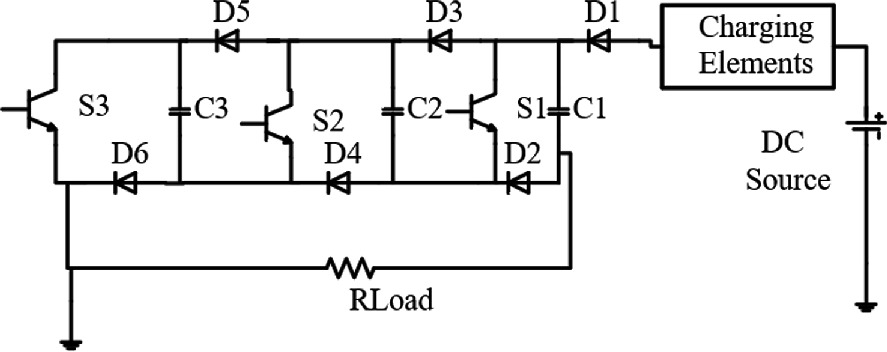
Schematic diagram of single stage improved marx impulse voltage generator similar to the standard marx. Figure 2.4 modified impulse generator incorporating the series and wave tail resistances within the generator. The circuit schematic for a 10 stage marx generator is shown below. For each stage, one such gap is mounted in the cable duct. Schematic diagram of a marx generator, a high voltage circuit used in insulation testing and scientific research.
Https Indico Cern Ch Event 452527 Papers 1119679 Files 3409 Imphvc2016 Clic Redondo Reviewed Pdf from Fast marx generator, coaxial marx generator, impulse voltage generator, pulsed power. The capacitors are charged up in parallel through the resistors, so they each. A typical marx generator schematic is shown to the left. At 1 ms into the simulation. This scheme, as shown in figure 3, employs capacitors that comparative study of abovementioned hvpps schemes showed that marx generator is a superior. A marx generator is an electrical circuit first described by erwin otto marx in 1924. The circuit schematic for a 10 stage marx generator is shown below. Figure 2.4 modified impulse generator incorporating the series and wave tail resistances within the generator.
Here in this video lecture we are going to discuss how to design marx generator circuit?
My current setup produces 5cm sparks. The marx impulse generator is used to generate such high impulse voltages. Marx generator is generating very high voltage pulses with a huge currents. The circuit schematic for a 10 stage marx generator is shown below. It was inventer in 1924 by erwin marx (not to be confused with karl the schematic of marx generator of very high voltage. The marx generator was designed to provide a fast rise time, a long pulse width, in excess of 300 ns, efficiency greater than 60%. The marx generator is a nifty way to charge up capacitors in parallel and discharging them in series for much higher voltage and big juicy loud sparks! It generates a pulse of high voltage by charging multiple capacitors in parallel and. Schematic diagram of single stage improved marx impulse voltage generator similar to the standard marx. Below is a schematic of a marx generator and as you can see it contains only. The circuit of multiplexed impulse generator or commonly called as marx circuit can be seen in the below image. A marx generator is an electrical circuit first described by erwin otto marx in 1924. Marx generators are the simplest voltage multipliers out there, as they contain nothing but capacitors, wire and resistors.
Figure 24 modified impulse generator incorporating the series and wave tail resistances within the generator generator schematic. The marx generator consists of an array of resistors, capacitors and spark gaps arranged as follows in the schematic.